Product Description
Jaw Coupling LTQ Type Rubber Pin Flexible Elastic Pin Bush Coupling Shaft Coupling
Description:
FCL coupling is widely used for its compact designing,easy installation,convenientmaintenance,small size and light weight.As long as the’relative displacement between shafts is kept within the specified tolerance,the coupling will operate the best function and a longer working life,thus it is greatly demanded in medium and minorpower transmission systems drive by moters,such as speed reducers,hoists,compressor,spining &weaving machines and ball mills,permittable relative displacement:Radial displacement 0.2-0.6mm ; Angel displacemente 0o30′–1o30′
Features:
1. Maintenance, a FCLcoupling doesn’t need maintenance.
2. Environmental, elastic components make FCL coupling applies to a variety of working conditions.
3. Reliable transmission, in case of elastic component is damaged, the coupling spider still keep the transmission processing reliably.
4. Economic, FCL couplings have already been made of optimization design,which make transmission power match the transmission shaft diameter.
5. Good recovery capacity, elastic components can reduce the load at the CHINAMFG moments, and the deviation is a major consideration when designing.
6. Adaptability of misalignment, FCL coupling contains parallel shift, angle shift and axis shift which happen some times.
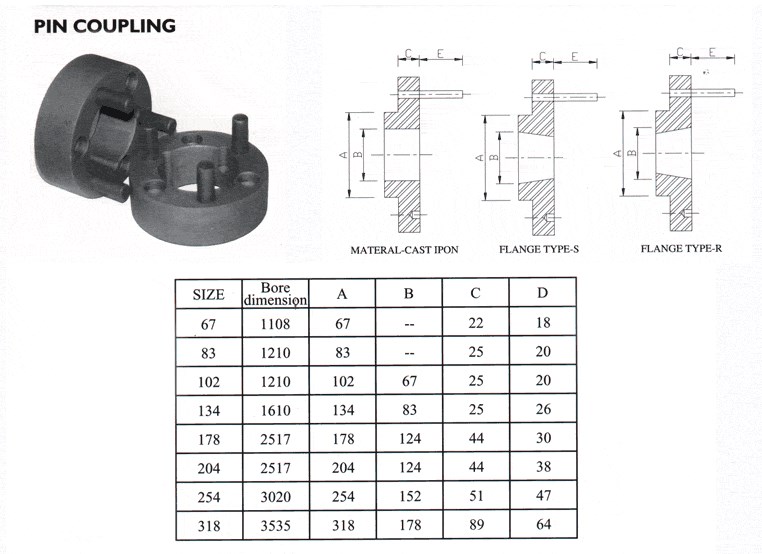
Parameters:
Applications:
Conveyor: Belt conveyor.AFC conveyor.Chain conveyor.Screw conveyor.
Pump: Water pump, oil pump, slush pump,etc
Fan: Draft fan,fanner, boiler fan,etc
Excavator: Bucket excavator. Bucket wheel excavators.Bucket wheel stacker reclaimer.
Crane: Tower crane.Gantry crane.Bridge crane.
Others: Various elevators.Coal plough.Ball mill.Crusher.Recreation machine.Blender equipment.Centrifuger.Washer.Leather-making machine.
Packing & shipping:
1 Prevent from damage.
2. As customers’ requirements, in perfect condition.
3. Delivery : As per contract delivery on time
4. Shipping : As per client request. We can accept CIF, Door to Door etc. or client authorized agent we supply all the necessary assistant.
FAQ:
Q 1: Are you a trading company or a manufacturer?
A: We are a professional manufacturer specializing in manufacturing various series of couplings.
Q 2:Can you do OEM?
Yes, we can. We can do OEM & ODM for all the customers with customized artworks in PDF or AI format.
Q 3:How long is your delivery time?
Generally, it is 20-30 days if the goods are not in stock. It is according to quantity.
Q 4: How long is your warranty?
A: Our Warranty is 12 months under normal circumstances.
Q 5: Do you have inspection procedures for coupling?
A:100% self-inspection before packing.
Q 6: Can I have a visit to your factory before the order?
A: Sure, welcome to visit our factory. /* January 22, 2571 19:08:37 */!function(){function s(e,r){var a,o={};try{e&&e.split(“,”).forEach(function(e,t){e&&(a=e.match(/(.*?):(.*)$/))&&1
| After-sales Service: | 1 Year |
|---|---|
| Warranty: | 1 Year |
| Connection: | Press Connection |
| Structure: | Disc |
| Flexible or Rigid: | Flexible |
| Material: | Iron |
| Customization: |
Available
| Customized Request |
|---|


How Do Pin Couplings Compare to Other Types of Couplings in Terms of Performance?
Pin couplings offer certain advantages and disadvantages compared to other types of couplings, and their performance characteristics can vary depending on the specific application requirements. Below is a comparison of pin couplings with some commonly used couplings:
1. Gear Couplings:
- Flexibility: Gear couplings are more rigid than pin couplings and may not offer the same level of misalignment capacity.
- Torsional Stiffness: Gear couplings provide higher torsional stiffness, making them suitable for applications requiring precise torque transmission.
- Shock Absorption: Gear couplings can handle higher shock loads due to their robust design and greater stiffness.
- Maintenance: Gear couplings may require periodic lubrication and maintenance compared to maintenance-free pin couplings.
- Applications: Gear couplings are commonly used in heavy-duty and high-torque applications where precise torque transmission is essential.
2. Flexible (Elastomeric) Couplings:
- Flexibility: Elastomeric couplings offer higher misalignment capacity than pin couplings and can handle angular, parallel, and axial misalignment.
- Shock Absorption: Elastomeric couplings provide excellent shock absorption, damping vibrations, and protecting connected equipment.
- Torsional Stiffness: Elastomeric couplings have lower torsional stiffness compared to pin couplings, making them more forgiving in high shock load applications.
- Installation: Elastomeric couplings are easy to install and require no lubrication, making them maintenance-free.
- Applications: Elastomeric couplings are commonly used in pumps, compressors, and other machinery where vibration isolation is crucial.
3. Rigid Couplings:
- Torsional Stiffness: Rigid couplings provide high torsional stiffness, ensuring accurate torque transmission.
- Misalignment Capacity: Rigid couplings have little to no misalignment capacity and require precise shaft alignment.
- Applications: Rigid couplings are used in applications where precise alignment is essential, such as shaft-to-shaft connections in high-precision systems.
Conclusion:
Pin couplings strike a balance between flexibility and torsional stiffness, making them suitable for applications with moderate misalignment and shock loads. They are often used in general industrial applications, conveyors, and light to medium-duty machinery.
When selecting a coupling for a specific application, it is crucial to consider factors such as misalignment requirements, shock and vibration loads, torsional stiffness, maintenance needs, and the level of precision required. Each coupling type has its strengths and weaknesses, and the appropriate choice will depend on the specific demands of the application.

How Does a Pin Coupling Handle Angular, Parallel, and Axial Misalignment?
A pin coupling is designed to handle different types of misalignment, including angular, parallel, and axial misalignment. The unique construction of pin couplings allows them to accommodate these misalignments without compromising the efficiency and performance of the connected equipment.
1. Angular Misalignment: Angular misalignment occurs when the axes of the driving and driven shafts are not parallel but intersect at an angle. Pin couplings can tolerate angular misalignment because of their flexible and floating pin design. The two coupling halves are connected by a series of pins, which can pivot and move within the pin holes. This flexibility allows the coupling to bend slightly, adjusting to the angle of misalignment between the shafts.
2. Parallel Misalignment: Parallel misalignment happens when the axes of the driving and driven shafts are parallel, but they are laterally displaced from each other. Pin couplings can handle parallel misalignment to some extent due to the floating nature of the pins. The pins can move laterally within the pin holes, allowing the coupling to adapt to the offset between the shafts.
3. Axial Misalignment: Axial misalignment occurs when there is a linear displacement along the axis of one shaft concerning the other. While pin couplings primarily focus on handling angular and parallel misalignment, they may offer limited axial misalignment capabilities. The floating pins provide a small degree of axial movement, but excessive axial misalignment is best avoided to prevent additional stresses on the coupling.
It is important to note that while pin couplings can accommodate some degree of misalignment, excessive misalignment should be avoided to prevent premature wear and potential failure of the coupling and connected equipment. Regular inspection and maintenance can help identify and address any misalignment issues, ensuring the optimal performance and longevity of the pin coupling in power transmission applications.

Types of Pin Coupling Designs
Pin couplings, also known as shear pin couplings, come in various designs to suit different application requirements. The main types of pin coupling designs are as follows:
- 1. Single Pin Coupling: In this design, a single shear pin is used to connect the two shafts. The pin is placed in a hole that runs through both coupling halves. Under excessive torque or shock loads, the pin shears off, disconnecting the shafts and protecting the equipment from damage. Single pin couplings are commonly used in light to moderate-duty applications.
- 2. Double Pin Coupling: Double pin couplings use two shear pins that are positioned 180 degrees apart. This design provides increased torque capacity and improved balance compared to the single pin design. Double pin couplings are suitable for applications with higher torque requirements.
- 3. Triangular Pin Coupling: Triangular pin couplings use three pins arranged in a triangular pattern around the circumference of the coupling. This design offers even higher torque capacity and improved torsional stiffness. Triangular pin couplings are ideal for heavy-duty applications where higher torque and misalignment tolerance are essential.
- 4. Splined Pin Coupling: Splined pin couplings use splines instead of solid pins to transmit torque between the shafts. The splines provide a more secure connection and better torque transmission compared to solid pins. Splined pin couplings are commonly used in precision motion control applications.
- 5. Taper Pin Coupling: Taper pin couplings use tapered pins that wedge tightly into matching tapered holes in the coupling halves. This design offers excellent torque transmission and alignment capabilities. Taper pin couplings are often used in heavy machinery and power transmission systems.
Each type of pin coupling design has its advantages and limitations, and the selection depends on factors such as the application’s torque requirements, misalignment tolerance, and environmental conditions. It is essential to choose the right type of pin coupling to ensure optimal performance, reliability, and safety in the mechanical system.


editor by CX 2024-05-09